











Select the correct Rayi Fixed Wing UAV Propeller by matching propulsion layout, motor data, aircraft clearance, thrust requirements, and operating conditions—then validate the choice with static and flight tests.
Choosing between a pusher and tractor propeller can directly affect UAV thrust, cooling, noise, endurance, payload capacity, and flight stability. In this guide, I will show you how to choose a pusher or tractor propeller for a UAV in a simple sequence, using motor specifications, propeller geometry, installation constraints, and measurable test results. With the right process, operators can avoid inefficient propulsion systems, excessive vibration, and costly redesigns.
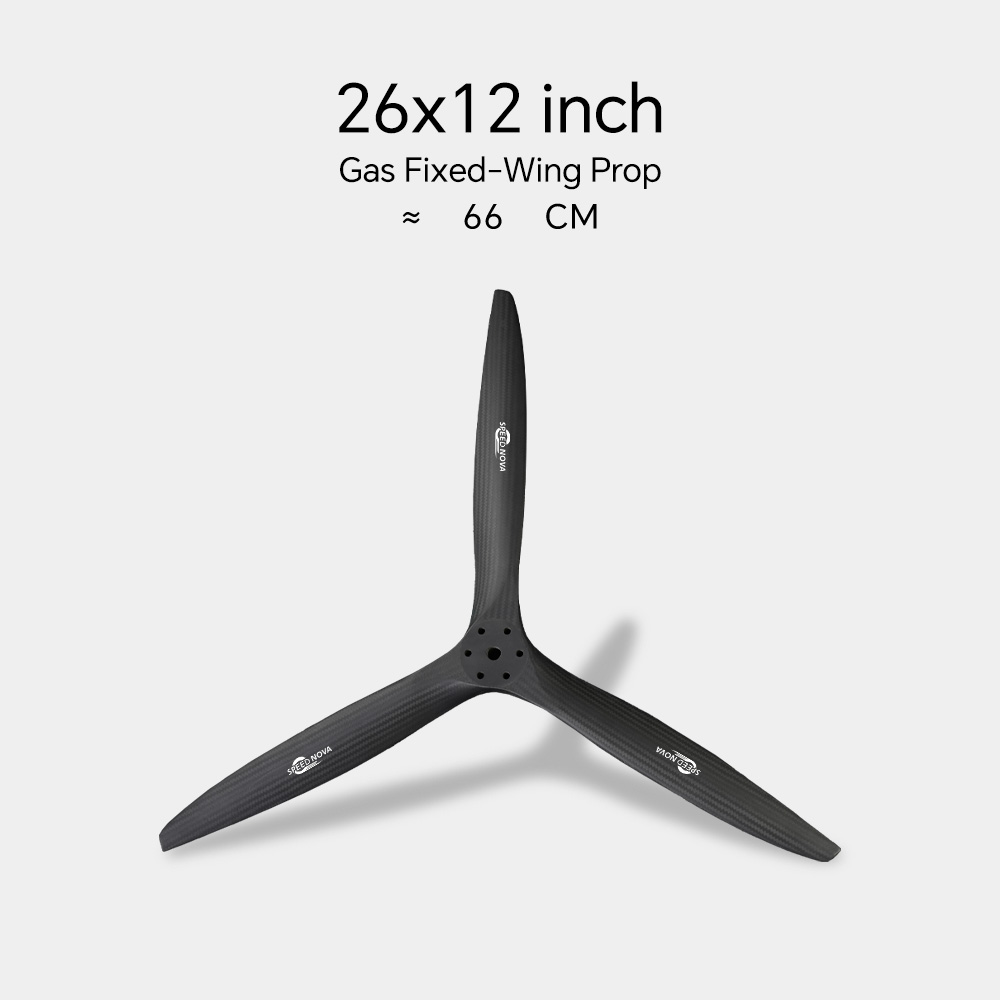
The first decision is determined by where the propeller is installed in relation to the motor and airflow.
A tractor propeller is mounted in front of the motor or fuselage and pulls the UAV through the air. This is the conventional arrangement used on many fixed-wing aircraft.
A tractor configuration can provide:
However, the propeller may be exposed to foreign-object damage during landing. It can also obstruct a forward camera, payload sensor, or other nose-mounted equipment.
A pusher propeller is installed behind the motor or fuselage and pushes the UAV forward. This layout is common on surveillance aircraft, mapping drones, and flying-wing platforms where the nose is reserved for cameras or sensors.
A pusher system can offer:
The main challenge is that the propeller may operate in disturbed airflow behind the fuselage, wing, landing gear, or motor mount. This can increase noise, vibration, and torque variation. A pusher fixed-wing drone propeller must therefore be selected with the aircraft’s wake and installation geometry in mind.
Before requesting a propeller from Rayi, record the following information. Propeller diameter and pitch should never be selected from aircraft weight alone.
Prepare these specifications:
For example, a 700 KV motor running from a 6S battery has a theoretical no-load speed of approximately:
700 × 22.2 V = 15,540 RPM
Actual loaded RPM will be lower because of propeller torque, voltage sag, winding resistance, and aerodynamic load. This calculation is only a starting point. Use a thrust stand or manufacturer-approved propeller data before flight testing.
Record:
A large-diameter, low-pitch propeller may be suitable for efficient climb and heavy payloads. A smaller-diameter, higher-pitch propeller may be more appropriate when ground clearance or high-speed cruise is the priority.
Propeller diameter controls the approximate size of the working disk, while pitch influences the theoretical forward distance traveled per revolution.
A larger diameter generally provides greater static thrust at lower disk loading, but it also increases:
A smaller diameter can support higher RPM and better installation clearance, but it may require greater rotational speed and produce lower static efficiency.
For a pusher installation, check the distance between the propeller arc and the fuselage, boom, wing, landing gear, and tail surfaces. Maintain a practical safety margin rather than designing for minimum clearance. The exact value depends on aircraft speed, vibration, material stiffness, and propeller flexibility, so Rayi or the airframe designer should validate the final geometry.
Theoretical pitch speed can be estimated as:
[ V_p = \\frac{RPM \\times Pitch}{1056} ]
For example, a propeller turning at 7,000 RPM with a 10-inch pitch has a theoretical pitch speed of approximately 66.3 mph before slip is considered.
Actual aircraft speed is lower because propeller slip, inflow distortion, and aerodynamic drag reduce efficiency. A propeller pitch that is too high may overload the motor during takeoff. A pitch that is too low may provide strong static thrust but limit cruise speed and increase RPM.
Use the following approach:
The best configuration depends on the aircraft’s mission rather than on a universal efficiency claim.
| Requirement | Tractor Propeller | Pusher Propeller |
|---|---|---|
| Forward camera field of view | May be restricted | Usually favorable |
| Motor cooling | Generally easier | May require ducting or airflow management |
| Static thrust | Often predictable | Can be affected by fuselage wake |
| Nose landing protection | More exposed | Often better protected |
| Propeller inspection | Easy access | May be less accessible |
| Rear fuselage packaging | Less suitable | Often suitable |
| Disturbed inflow risk | Lower | Higher behind fuselage or wing |
| Acoustic signature | Depends on aircraft geometry | May direct noise toward the rear or wing |
A tractor propeller is often the safer starting point for a conventional airframe because it receives relatively clean air. A pusher propeller is often the better packaging solution when the UAV requires a clear nose, rear-mounted motor, or protected forward payload.
For a pusher system, avoid placing the propeller immediately behind a thick fuselage, blunt motor mount, or sharp wing trailing edge unless the design has been validated. These features can create nonuniform inflow and periodic blade loading.
A propeller is not interchangeable simply because its diameter and pitch are correct.
Confirm:
For a tractor aircraft, the propeller normally faces forward into the incoming airflow. For a pusher aircraft, the propeller may require a pusher-specific blade orientation or a reversed rotation arrangement. Installing a tractor propeller incorrectly on a pusher motor can reduce thrust and increase aerodynamic losses.
Measure the propeller disk in CAD or with a physical template. Check for:
For production UAVs, I recommend creating a propeller clearance drawing with dimensions recorded to at least 0.01 mm in the CAD model, while recognizing that the real assembly tolerance and blade flexibility must also be validated physically.
The correct aerodynamic design can still fail if the propeller has poor dimensional accuracy or imbalance.
Common UAV propeller materials include:
Material selection should consider temperature, UV exposure, moisture, chemical contact, and expected RPM. A high-speed fixed wing UAV propeller requires sufficient stiffness to limit pitch deformation and blade flutter.
When evaluating Rayi or another propeller supplier, request:
For precision UAV components, ask whether critical dimensions are checked to a tolerance of 0.01 mm, whether each unit receives 100% visual inspection, and whether the supplier can provide a documented response within 24 hours for technical inquiries. These figures should be verified in the supplier’s quality agreement rather than assumed.
Relevant quality references may include:
These standards do not automatically certify a propeller for flight. They provide a framework for material, balance, and manufacturing control. The final UAV system still requires its own propulsion and flight validation.
Do not rely only on theoretical calculations. A propeller can appear suitable on paper but overload the motor in real conditions.
At minimum, record results at:
A practical operating point should produce the required thrust without exceeding the motor, ESC, battery, or propeller limits. Leave an engineering margin instead of operating continuously at the absolute maximum rating.
Static testing is useful for detecting overload and comparing propellers, but it does not perfectly represent flight. In forward motion, the propeller experiences advance ratio, reduced angle of attack, and different inflow conditions.
Pusher systems require additional attention because the propeller may receive turbulent air. Validate the selected fixed-wing drone propeller during:
Monitor vibration with an accelerometer or flight controller logging system. Excessive vibration can affect the IMU, camera stabilization, autopilot performance, and composite airframe joints.
Likely causes include excessive diameter, excessive pitch, high battery voltage, or insufficient propeller clearance.
Solutions:
Possible causes include low static thrust, a propeller operating outside its efficient range, excessive aircraft weight, or a pusher propeller operating in disturbed airflow.
Solutions:
Common sources include propeller imbalance, hub misalignment, motor-shaft runout, loose hardware, or blade deformation.
Solutions:
This may result from excessive pitch, high current at cruise throttle, aerodynamic drag, or an inefficient pusher installation.
Solutions:
A clear technical data sheet makes the selection process faster and reduces sample errors. Send Rayi the following information in one request:
Ask for two or three candidate propellers rather than selecting a single size without testing. A supplier with UAV application experience should be able to explain the trade-off between diameter, pitch, RPM, thrust, current, and acoustic performance.
Useful tools include:
Calculators are valuable for screening options, but measured thrust and flight data should control the final decision.
Before approving a Rayi fixed wing UAV propeller, complete these checks:
The best answer to How to Choose a Pusher or Tractor Propeller for a UAV is not simply “choose the largest propeller” or “use a pusher for better packaging.” The correct choice is the one that matches the motor operating envelope, aircraft geometry, mission speed, cooling requirements, and measurable thrust performance.
Rayi can be evaluated as a fixed wing UAV propeller supplier by requesting application-specific recommendations, dimensional data, balance requirements, material information, and test documentation. Whether your aircraft uses a pusher or tractor layout, begin with the ten-step checklist, validate the propeller on a thrust stand, and then confirm performance in flight. This process helps UAV manufacturers reduce redesign risk, protect sensitive payloads, improve endurance, and establish a reliable production specification.
Aug. 13, 2026

