











Choosing a fixed-wing drone propeller is not simply a matter of selecting the largest or fastest blade. A rear-mounted pusher propeller for fixed-wing UAVs changes airflow, cooling, balance, noise, and payload clearance. This guide compares pusher versus tractor propeller efficiency and explains how to choose a pusher propeller for a fixed-wing drone using measurable factors such as static thrust, propeller disk loading, and torque reaction. It is intended for engineers, operators, and builders evaluating a fixed-wing UAV, electric motor, and aerodynamic drag as one integrated system.
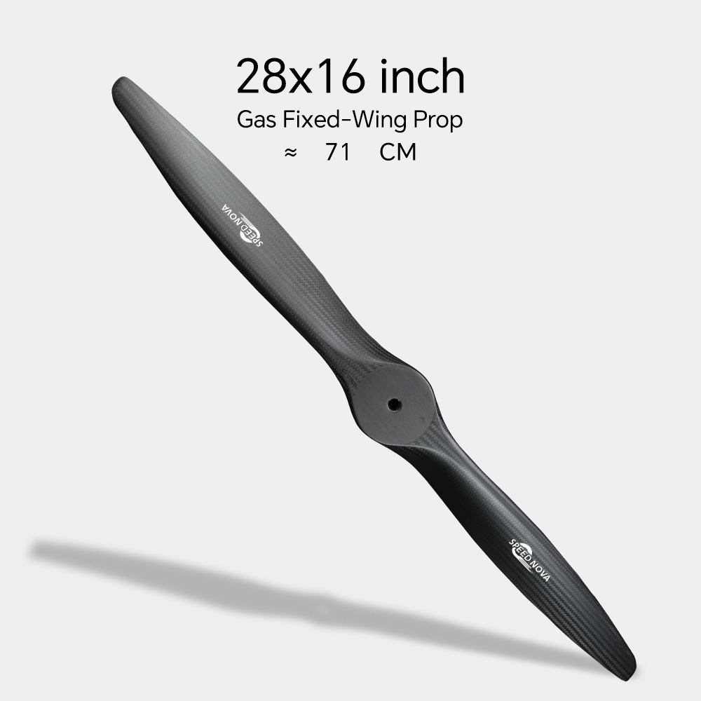
A pusher propeller is mounted behind the motor or fuselage and produces thrust by pushing the aircraft forward. In a conventional tractor layout, the propeller is installed at the nose and pulls the aircraft through the air. Both arrangements can deliver similar thrust when the motor, propeller diameter, pitch, battery voltage, and operating point are comparable.
The important difference is the propeller’s aerodynamic environment. A nose-mounted tractor propeller normally operates in relatively undisturbed air. A rear-mounted pusher may operate behind the fuselage, wing, landing structure, payload bay, or tail boom. The propeller can therefore receive non-uniform inflow, which may affect efficiency, vibration, noise, and blade loading.
A propeller accelerates air rearward and creates a forward reaction force. Its performance is commonly evaluated with:
For level flight, the propeller does not need to provide the aircraft’s maximum static thrust continuously. It must provide thrust equal to aerodynamic drag at the selected cruise speed, while retaining enough margin for takeoff, climb, turns, and wind conditions.
The most visible advantage is an unobstructed nose. A pusher layout can leave the forward fuselage available for:
This arrangement can reduce the risk of propeller blades appearing in a camera’s field of view. However, the camera still needs protection from vibration, motor electromagnetic interference, and fuselage flexure. A clear image path does not automatically mean stable imagery.
With no front motor and propeller, designers can create a removable nose module or a larger forward payload bay. This is useful when operators change sensors between missions. It can also make the center of gravity easier to manage if the battery is placed near the aircraft’s longitudinal balance point.
For example, an aircraft designed with a 25% to 33% mean aerodynamic chord center-of-gravity target must keep the loaded CG inside the manufacturer’s approved range. A forward sensor, battery, or payload can move the CG substantially, so the pusher layout should be evaluated with a mass-and-balance calculation rather than judged by appearance.
A rear propeller is less likely to strike the ground during a conventional belly landing on a flat field. This can reduce damage to the blade and motor in operations where a landing gear system is not used. It does not eliminate impact risk: tall grass, uneven terrain, tail-first touchdown, or a steep landing attitude can still damage the pusher propeller.
Operators should maintain a measured ground clearance margin. The required clearance depends on blade diameter, landing attitude, skid compression, and terrain. A fixed number cannot be applied safely to every aircraft.
A pusher configuration can allow a streamlined nose and a sensor-integrated fuselage. This may reduce local interference around the nose, but the total aircraft drag is not automatically lower. The rear propeller, motor mount, cooling openings, tail boom, and wake interaction can add drag elsewhere.
Aircraft-level drag should be measured or estimated using the complete airframe. A nose that looks smoother does not prove a lower drag coefficient.
A rear motor can be installed between twin booms, behind a fuselage, or at the rear of a flying wing. This creates packaging options that are difficult to achieve with a nose-mounted motor. It can also keep the propeller away from a forward payload release mechanism.
Rayi and other aerospace component suppliers may offer different propeller, motor, and mounting options, but compatibility must be verified from actual specifications: diameter, pitch, rotation direction, shaft size, maximum RPM, mass, thrust curve, and power input.
The largest technical concern is non-uniform inflow. A pusher propeller may ingest the fuselage or wing wake. One blade can encounter faster or slower air than another during each revolution, producing periodic thrust variation and vibration.
This effect is especially important when the propeller is close to:
There is no universal percentage penalty for pusher efficiency. Wind-tunnel tests and computational studies show that the result depends on spacing, geometry, angle of attack, advance ratio, propeller diameter, and blade design. A well-integrated pusher can perform acceptably, while a propeller placed directly in a strong wake can lose efficiency and generate vibration.
A front-mounted motor is often exposed to clean airflow. A rear-mounted motor may sit inside a fuselage or behind a wing, where cooling air is warmer and slower. Brushless electric motors convert part of their electrical input into heat; the motor and electronic speed controller must reject that heat during climb and cruise.
Motor temperature should be checked with a thermocouple or a reliable onboard temperature sensor during the highest-power phase. A practical design should remain below the motor, ESC, battery, and wiring temperature limits specified by their manufacturers. Do not treat a short bench test as proof of adequate cooling: a static test can create a different airflow condition from forward flight.
The rear position may protect the propeller during a nose-first landing but expose it during transport, launch, tail placement, or hand recovery. A handler can contact the blade while holding the aircraft, and a tail skid can transfer impact energy into the motor mount.
Useful safeguards include a removable propeller, a physical propeller guard where aerodynamically acceptable, a transport case, and a written “propeller removed before handling” procedure. Never rely only on the electronic throttle lock; remove the battery before working near the propeller.
The propeller must have adequate clearance from the horizontal stabilizer, vertical stabilizer, elevator, rudder, booms, and fuselage. Clearance is not only a static measurement. Blade flex, motor mount deflection, vibration, thermal expansion, and crash deformation can reduce the gap during operation.
Insufficient clearance can cause blade strikes and may also place the tail in a highly turbulent slipstream. This can increase control-surface vibration and make flight-test data less repeatable.
A pusher propeller can produce noticeable noise when its slipstream interacts with the fuselage, wing, or tail. The sound level depends on blade tip speed, blade loading, RPM, airframe resonance, and the distance and direction of the observer. A larger propeller turning at a lower RPM can reduce tip speed for the same approximate thrust, but it may not fit the airframe or motor.
Propeller balance is critical. A dynamic imbalance can damage bearings, loosen fasteners, blur camera footage, and fatigue the motor mount. Static balancing is useful, but dynamic vibration testing is more reliable for a complete aircraft.
Hand launching a pusher UAV requires a safe grip that does not place the operator’s hand near the rear propeller. The launch procedure must also prevent the aircraft from entering a stall immediately after release. For belly landings, the aircraft should touch down without tail-first contact and should use a skid or fuselage shape that protects the propeller.
For aircraft operated from short strips, compare the pusher layout with a tractor layout using actual takeoff distance, climb rate, landing speed, and recovery damage records. Static thrust alone does not predict takeoff performance.
| Factor | Rear-mounted pusher | Front-mounted tractor | What to measure |
|---|---|---|---|
| Forward sensor visibility | Usually favorable | May be limited by the propeller arc | Camera field of view and blade position |
| Motor cooling | May be difficult behind the fuselage or wing | Often simpler with direct airflow | Motor and ESC temperature at maximum continuous power |
| Propeller inflow | May be disturbed by the airframe wake | Usually cleaner at the nose | Thrust, current, vibration, and inflow uniformity |
| Ground contact during belly landing | Often lower nose-strike risk | Higher risk unless protected by landing gear or skid design | Ground clearance through the full landing attitude |
| Operator safety during hand launch | Requires a rear-safe grip and procedure | Requires clearance from the front propeller | Launch sequence, grip position, and emergency cutoff |
| Noise and vibration | May increase near tail and fuselage surfaces | May transmit vibration through the nose structure | Measured vibration, RPM, and sound pressure level |
This comparison does not identify one universal winner. The best arrangement is the one that meets the aircraft’s mission requirements with acceptable temperature, vibration, noise, structural load, and maintenance results.
Record the aircraft’s maximum takeoff mass, target cruise speed, stall speed, launch method, climb requirement, payload mass, and expected density altitude. A propeller selected only from a static-thrust chart may perform poorly in forward flight because the propeller’s advance ratio changes with airspeed.
For electric propulsion, estimate the required battery energy using:
Energy required in watt-hours = average electrical power in watts × flight time in hours.
Include reserve energy and the power used by avionics, payloads, and communications equipment. Battery capacity printed on a label is not the same as usable energy under the manufacturer’s discharge and reserve limits.
Use the motor manufacturer’s recommended propeller range and verify the combination with a wattmeter or propulsion test stand. Confirm:
A larger or higher-pitch propeller can increase thrust, but it can also increase current and heat. The relationship is not safely predictable from diameter alone, so test data is required.
Some propellers are designed for normal tractor rotation, while others are intended for reverse or pusher rotation. Follow the propeller manufacturer’s instructions. Reversing a motor’s rotation is not always equivalent to using a correctly designed pusher propeller, particularly when blade airfoil geometry, pitch distribution, and labeling are considered.
Confirm the propeller’s intended direction by checking the manufacturer’s documentation, not merely by reading the size markings on the blade.
Draw the complete propeller arc and include a margin for blade flex and mount movement. Inspect clearance at maximum elevator and rudder deflection, during landing compression, and after applying the expected motor torque.
If possible, test several longitudinal positions. Moving the propeller away from the trailing edge or fuselage can improve inflow quality, but it may increase tail-boom bending loads or change the aircraft’s center of gravity.
Use a calibrated thrust stand or load cell rather than estimating thrust from motor RPM. At each propeller setting, record:
Repeat the test after the propulsion system reaches a representative operating temperature. A cold motor can produce results that do not represent a long climb.
Static thrust does not equal climb thrust in flight. Conduct a controlled flight test and compare climb rate, cruise current, airspeed, battery temperature, motor temperature, vibration, and noise. Repeat the test in similar weather conditions so that wind and air density do not conceal changes in performance.
For mapping or inspection missions, evaluate image sharpness and georeferencing quality. A pusher propeller that produces acceptable thrust but excessive vibration may still be unsuitable for a camera-equipped aircraft.
Provide a defined inlet and outlet path instead of relying on random gaps around the fuselage. The outlet should not be blocked by a battery, payload tray, or wiring bundle. Confirm airflow with temperature measurements during sustained high-power operation.
Balance the propeller, inspect the shaft and hub, stiffen the motor mount, and use locking hardware appropriate for the vibration environment. Soft mounts can isolate high-frequency vibration, but excessive flexibility can allow propeller clearance to change under load.
Reduce unnecessary RPM where the motor and propeller data support it, avoid placing the blade tips close to flat surfaces, and maintain accurate blade balance. Do not reduce RPM so far that the propeller becomes overloaded or the aircraft cannot maintain the required speed.
Use a removable blade or folding-propeller system only if it is approved for the motor’s RPM and thrust direction. Add a preflight inspection covering cracks, leading-edge damage, hub security, shaft straightness, and tail clearance. Any blade that has suffered a ground strike should be inspected or replaced according to the manufacturer’s guidance.
A rear-mounted pusher is worth considering when a mission needs a clear forward sensor view, a modular nose, lower risk of nose-propeller ground contact, or a twin-boom or flying-wing architecture. It is less attractive when the aircraft requires simple motor cooling, frequent hand handling, very low vibration for imaging, or maximum propeller exposure to clean air.
The decision should be based on measured system performance rather than the pusher label. Compare two complete configurations at the same aircraft mass and mission speed. Record watt-hours per kilometer or per flight hour, climb rate, temperature, vibration, noise, maintenance events, and landing damage. If the pusher configuration meets the requirements with a documented safety margin, its packaging benefits can outweigh its aerodynamic and maintenance disadvantages.
Not necessarily. The motor and propeller can produce similar thrust in a controlled test, but a pusher installed in the wake of a fuselage or wing may have lower propulsive efficiency or higher vibration. The airframe installation, not the word “pusher” alone, determines the result.
They are not inherently quieter. Noise depends on RPM, blade loading, tip speed, blade shape, and interaction with the fuselage and tail. Measure sound pressure level at a defined distance and throttle setting if acoustic performance matters.
Do not assume that reversing a normal propeller gives the same performance as a purpose-designed pusher propeller. Check the manufacturer’s rotation and installation instructions. Also verify the motor direction, cooling airflow, propeller markings, and maximum RPM.
Common problems include insufficient tail clearance, motor overheating, loose mounting hardware, propeller imbalance, and damage during handling or landing. A preflight inspection and temperature test can identify many of these issues before regular operation.
There is no single safe clearance value for every UAV. The required gap depends on propeller diameter, blade flex, mount stiffness, tail movement, landing loads, and structural deformation. Use the airframe manufacturer’s specification and verify the clearance under realistic operating conditions.
No. Static thrust is useful for comparing test points, but a fixed-wing aircraft normally operates with forward airspeed. Cruise current, climb rate, airspeed, motor temperature, battery voltage sag, vibration, and endurance should also be measured in flight.
Rayi may be considered as a component source, but suitability must be confirmed from the exact product data. Request the propeller diameter, pitch, rotation direction, material, maximum RPM, mass, hub dimensions, thrust data, and recommended motor range before purchase. Match those values to the aircraft’s propulsion test results.
Rear-mounted pusher propellers solve specific integration problems rather than providing a universal efficiency advantage. They can clear the nose for sensors, simplify payload access, and reduce some belly-landing risks, while introducing wake ingestion, cooling, vibration, tail-clearance, and handling concerns. Before selecting a rear-mounted pusher propeller for fixed-wing UAVs, compare pusher versus tractor propeller efficiency at the real cruise condition and verify how to choose a pusher propeller for a fixed-wing drone through static thrust, propeller disk loading, torque reaction, temperature, and flight-test data. A Rayi-sourced component should be accepted only after those measurements confirm that the complete aircraft meets its mission and safety limits.
Suggested technical references: NASA, “Beginner’s Guide to Aerodynamics”; UIUC Applied Aerodynamics Group propeller data; FAA Advisory Circular AC 107-2A for small unmanned aircraft operational guidance; and the specific motor, ESC, battery, and propeller manufacturer manuals.
Aug. 17, 2026

