











When a large-diameter UAV propeller operates too close to a frame arm, battery housing, neighboring rotor, wall, or the ground, the aircraft may lose lift precisely when it needs it most. Pilots may notice longer takeoff runs, rising motor temperature, unstable hover, or sudden vibration. The practical answer is not to increase throttle blindly: measure the large-diameter UAV propeller blade clearance, identify the obstruction, and restore a controlled airflow path. This article explains how to measure drone propeller clearance, why rotor interference changes thrust, and how tip vortex, induced velocity, and dynamic balance affect safety.
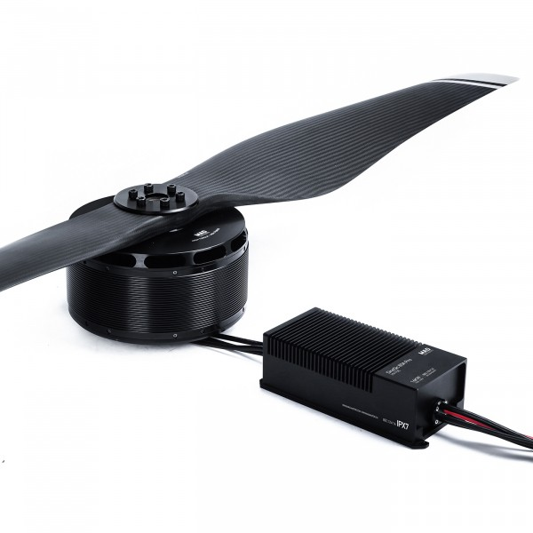
Blade clearance is the shortest safe distance between the rotating blade envelope and any nearby object. Depending on the aircraft, this may include:
Static clearance is the gap measured while the aircraft is powered off. Dynamic clearance is the actual gap under rotation, vibration, blade flex, motor deflection, landing-gear compression, and flight loads. Dynamic clearance is the more important value. A propeller can appear safely spaced in a workshop and still approach an arm or neighboring blade during a high-throttle maneuver.
There is no single universal clearance number for every UAV. The correct limit depends on propeller diameter, blade stiffness, rotational speed, motor mount rigidity, frame geometry, payload, temperature, and the manufacturer’s engineering validation. For that reason, a design should follow the propeller and airframe supplier’s tested minimum rather than an informal rule such as “one inch is always enough.”
A propeller accelerates air through its disk. If the disk is close to a flat frame plate, fuselage, wall, or ground, the air cannot expand and move away normally. The obstruction increases local pressure and redirects the flow. The result is a non-uniform velocity field across the blade span.
In engineering terms, thrust is commonly expressed as:
T = CTρn2D4
Here, T is thrust, CT is the thrust coefficient, ρ is air density, n is revolutions per second, and D is propeller diameter. Clearance problems generally reduce the effective thrust coefficient, CT, even when motor speed remains unchanged. Increasing throttle may therefore raise electrical power and heat without producing the expected lift.
The exact thrust reduction cannot be stated without testing. It varies with the obstruction’s shape, distance, angle, propeller pitch, and operating point. A claim such as “a 10% smaller gap always causes a 20% thrust loss” would not be technically reliable.
At the blade tip, high-pressure air moves toward the low-pressure side and forms a rotating tip vortex. A nearby structure can distort this vortex, while a nearby rotor can ingest the disturbed wake. The second rotor then operates in air that already has axial and rotational velocity.
This rotor interference can produce several effects:
Interference is not automatically harmful in every coaxial or multirotor design. Some aircraft are intentionally designed around overlapping rotor disks, and the manufacturer may compensate through propeller pitch, spacing, motor rotation direction, and control software. The safety issue arises when the overlap or nearby obstruction is outside the tested configuration.
Near the ground, a rotor can generate more static thrust for a given speed because the ground limits the development of the downward flow. This is called ground effect. However, a low fuselage, landing skid, wall, or uneven surface can also create recirculation and asymmetric inflow. A pilot may observe a brief lift increase near a flat surface, followed by unstable yaw or roll when the aircraft moves away.
Ground effect should therefore be treated as an operating condition, not as a reason to reduce the safety gap beneath a propeller.
During acceleration, braking, and rapid attitude changes, a blade does not behave like a perfectly rigid disk. Centrifugal loading, aerodynamic loading, temperature, manufacturing variation, and hub movement can change its position. A flexible composite blade may also experience torsional deformation as aerodynamic load changes.
Insufficient clearance leaves less margin for:
A blade strike can damage the propeller, motor, arm, payload, or nearby people. Even without contact, repeated close passage can create vibration that accelerates fatigue in the hub, fasteners, and carbon-fiber structure.
Flight controllers use gyroscopes and accelerometers to estimate aircraft motion. A poorly spaced or damaged propeller can generate periodic vibration that enters those sensors. The controller may interpret the vibration as movement and continually adjust motor output.
The pilot may then see oscillation, drifting altitude, unexpected yaw, or a warning related to motor output. A larger clearance does not solve every vibration problem—propeller balance, shaft runout, bearing condition, and frame stiffness also matter—but inadequate clearance can be the original cause of the disturbance.
Heavy-lift operations place greater demand on the propulsion system. If a rotor loses part of its expected thrust because of airflow blockage, the flight controller may compensate with higher motor speed. That can increase current draw and reduce battery endurance.
For example, if a propulsion system normally requires 80% of its tested maximum thrust reserve during a climb, a clearance-related loss may leave less reserve for wind gusts or an engine-out response. The precise reserve must be calculated from the aircraft’s flight-test data; it should not be guessed from motor size alone.
Clearance problems often appear as a group of symptoms rather than one obvious failure:
| Observed symptom | Possible clearance-related cause | What to check |
|---|---|---|
| Higher throttle needed to hover | Airflow blocked by a frame, payload, or neighboring rotor | Propeller disk position and motor RPM at hover |
| Motor current rises without a payload change | Disturbed inflow or blade rubbing risk | Current, RPM, temperature, and visual clearance |
| Periodic vibration or buzzing | Rotor interference, blade damage, or dynamic imbalance | Blade tracking, hub seating, fasteners, and vibration data |
| Yaw or roll instability | Unequal thrust caused by different local airflow | Left/right rotor spacing and obstruction symmetry |
| Scuff marks or chipped blade tips | Dynamic clearance is smaller than static clearance | Blade envelope under maximum approved operating conditions |
Remove the flight battery, disconnect the motor power system where practical, and secure the airframe on a level work surface. Never measure a powered propeller with your hands near the blade path. Remove loose objects and confirm that the propeller cannot start unexpectedly.
Rotate the propeller slowly by hand and measure the shortest distance from the blade tip, leading edge, and trailing edge to every nearby structure. A flexible ruler, feeler gauge, or calibrated clearance gauge can be used for preliminary inspection. Record the location, not just the smallest number.
Check the full 360-degree rotation. A propeller may have adequate clearance at one blade position and a dangerously narrow gap at another because of a bent shaft, incorrect hub seating, or an off-center motor mount.
Static measurement is only the starting point. Review the propeller manufacturer’s blade-deflection data and the airframe’s structural analysis where available. Consider:
For a production aircraft, use a guarded test stand and non-contact measurement equipment such as a high-speed camera, laser displacement sensor, or validated optical tracking system. Do not operate an unguarded large-diameter propeller near people merely to observe its movement.
Measure the same points on every motor. A single rotor with a different gap can explain a persistent yaw correction or unequal motor temperature. Compare motor RPM, current, thrust, and vibration at the same test condition. The objective is to find a repeatable difference, not to rely on sound or touch.
Use a restrained test stand with a propeller guard or a remote test area suitable for the aircraft’s energy level. Record thrust, voltage, current, RPM, motor temperature, and vibration at defined throttle points. A valid comparison changes only one variable—for example, the clearance—while keeping the propeller model, battery voltage, and test environment consistent.
Stop immediately if the test shows rubbing, abnormal vibration, unstable RPM, rapidly increasing temperature, or a current value above the motor and electronic speed controller limits.
The most reliable solution is often geometric. Move the battery tray, payload mount, arm, landing gear, or wiring away from the propeller disk. Avoid placing broad flat surfaces directly in the strongest part of the propeller wash. Rounded transitions and streamlined supports can reduce abrupt airflow separation, but they do not replace adequate physical spacing.
A larger diameter or higher-pitch propeller is not automatically an upgrade. It may increase the blade envelope, motor torque demand, current draw, and structural load. Confirm that the propeller diameter, pitch, rotation direction, hub bore, adapter, and motor are approved as a matched set.
Do not trim a blade tip to create space. Removing material changes mass distribution, chord, aerodynamic loading, and balance. Replace a damaged or incorrectly sized propeller with the manufacturer-approved part.
If the static gap is acceptable but the dynamic gap is not, inspect the motor plate, arm joints, fasteners, bearings, and hub. Use the specified torque and locking method. A rigid mount helps preserve alignment, while excessive stiffness in one part of a flexible frame can transfer loads elsewhere. Any structural modification should be followed by a new vibration and thrust test.
For a Rayi large UAV propeller, use the product drawing, approved motor pairing, operating RPM range, and installation instructions supplied for the specific model. The relevant clearance is tied to the complete propulsion system, not to the propeller diameter alone. Rayi product support can help confirm whether a proposed frame, motor, or payload arrangement matches the tested configuration.
| Area | Insufficient or unverified clearance | Properly validated clearance |
|---|---|---|
| Thrust | Thrust coefficient may fall because of blocked or disturbed inflow. | Thrust is measured across the approved RPM and payload range. |
| Energy use | Higher throttle and motor current may reduce endurance. | Power consumption is compared with baseline test data. |
| Vibration | Rotor interaction and blade strikes may excite the frame. | Propeller balance, mount stiffness, and vibration are checked together. |
| Maintenance | Scuffing and fatigue damage may remain hidden until failure. | Inspection points and replacement limits are documented. |
| Flight safety | Less reserve remains for wind, payload changes, or control corrections. | The aircraft is operated within tested configuration and environmental limits. |
The aerodynamic relationship used in this article is consistent with standard propeller analysis: thrust depends on air density, rotational speed, diameter, and the experimentally or computationally determined thrust coefficient. The UIUC Applied Aerodynamics Group publishes propeller performance data, while NASA Glenn explains the basic relationship between propeller rotation, accelerated airflow, and thrust. These resources support the physics, but they do not provide one universal UAV clearance percentage.
For operational safety, operators should also consult the applicable aviation authority and the aircraft manufacturer. In the United States, FAA Advisory Circular AC 107-2A provides guidance related to small unmanned aircraft operations under Part 107. Larger or certified aircraft may fall under different rules. Local requirements, manufacturer instructions, and the aircraft’s approved flight manual take priority.
Important fact-check about the requested eye-health statistic: the statement that the “China Eye Health White Paper (2022)” surveyed 32,000 children aged 6–12 in 27 provinces and found myopia rising from 53.6% in 2018 to 59.1% in 2021 could not be reliably verified from a clearly identified official publication or primary dataset. It is unrelated to UAV blade clearance and should not be presented as evidence in this article. Official Chinese health authorities have published different national myopia-survey figures for specific years and age groups, so the numbers should not be substituted without a traceable report title, issuing institution, methodology, and page reference.
There is no universal safe value. The required gap must account for blade flex, motor-mount movement, frame tolerances, vibration, and the manufacturer’s tested installation. Use the approved product drawing and verify dynamic clearance rather than relying only on a static measurement.
Yes. A frame arm can obstruct or redirect airflow through part of the rotor disk. The resulting thrust change depends on the arm’s size, position, shape, and distance from the blade. It should be confirmed with controlled thrust testing rather than estimated from appearance alone.
No. The thrust equation contains a diameter term, but the actual thrust coefficient depends on propeller geometry, RPM, air density, inflow, and motor capability. A larger propeller can overload the motor or create insufficient structural clearance.
A frame change may place a support, battery, payload, or neighboring rotor in the propeller wash. It may also increase weight or alter the center of gravity. Compare hover thrust, motor current, RPM, and vibration before and after the modification.
A guard can reduce the chance of direct contact in some applications, but it can also obstruct airflow, add weight, and alter thrust. A guard is not a substitute for the clearance and flight-test requirements specified by the aircraft manufacturer.
Check it during initial assembly, after any hard landing or structural repair, whenever the payload or propeller changes, and as part of routine maintenance. Large-diameter propellers deserve additional inspection because their blade envelope and stored rotational energy are greater.
Insufficient blade clearance is not merely a cosmetic design problem. It can disturb the propeller wash, reduce the effective thrust coefficient, increase motor load, amplify vibration, and remove the reserve needed for safe control. The most dependable process is to measure static clearance, account for dynamic movement, compare all rotors, and confirm the final configuration with controlled thrust and vibration testing.
For operators evaluating a safe clearance for heavy-lift drone propellers, the key value is verified performance rather than a generic number. Keep the rotor disk clear, use matched propulsion components, document the test condition, and follow the approved Rayi configuration. To review compatible Rayi propeller solutions or discuss a specific airframe layout, visit Rayi Aero and request configuration guidance before your next flight test.
Aug. 18, 2026

